Archive for Illustrations

Morphometric measurements from vector images

I’ve been trying to find a good method for quantifying just how spiny any given ant species is. Among Pheidole ants, we see this interesting phenomenon where certain clades have developed elaborate spines and armature relative to the rather conservative morphology of their relatives. This ‘spinescent’ morphotype has evolved independently in at least four Pheidole lineages.

Morphometric measurements from vector images from Eli Sarnat on Vimeo.

So how to measure spinescence? Ideally we’d have 3D tomography of representative specimens from each species, but that’s not very feasible. Using a stage micrometer to measure spine length relative to something like head width is another option, but it is really difficult to account for the curves and bifurcations in some of the structures.

My solution is to create a spinescence index, defined as the ratio of spine perimeter to body perimeter. In other words, what percentage out the specimen’s 2D perimeter is devoted to spines? It’s not a perfect solution, but it’s the best I’ve come up with in terms of accuracy and feasibility.

New line drawings for undescribed Fijian Pristomyrmex

Here are a few line drawings I am working on for the description of an undescribed species of Fijian Pristomyrmex. In the Ants of Fiji monograph, this species is listed as Pristomyrmex sp. FJ02.

Full face view of Pristomyrmex sp. FJ02. Line drawings can allow for better representation of important taxonomic features compared to specimen photographs. For example, the mandibular tooth structure is essential for Pristomyrmex species identification. The mandibular teeth on the specimen photograph used as a template for this illustration were obscured and difficult to see. The line drawing shows them quite clearly.

Rendering the characteristic foveae (circular depressions) of Pristomyrmex was a bit challenging, and I am sure my method could use some improvement. I began by using the Ellipse Tool to get the basic shapes, and then rotated them according to the template specimen. Next I used the eraser tool to break the foveae that appeared somewhat shallow. I then selected all the ‘broken’ foveae and applied a stroke profile that tapers strongly on both ends. For the ‘unbroken’ foveae I selected each individually and used the Width Tool to constrict the ellipses at a single point.

Profile of Pristomyrmex sp. FJ02. Of the over 50 known species of Pristomyrmex, this is only the second that lacks propodeal spines. The other, P. inermis, occurs in New Guinea.

I also used a new technique for the hairs on this illustration. I decided to use the Outline Stroke function for all of the hairs, and selected a white outline stroke. This allows for a white break where hairs overlap the ant profile and other strokes.

Antkey release

Andy Suarez and I are excited to announce the release our Antkey.org project. The project was funded by USDA-APHIS-PPQ-CPHST and the Encyclopedia of Life (EOL) Rubenstein Fellowship program to provide an online identification guide to invasive, introduced and commonly intercepted ants.

Download USDA Antkey Announcement


Frontpage of the Antkey.org site


Over 15,000 species of ants have been described, and more than 200 have established populations outside of their native ranges. A small subset of these have become highly destructive invaders including five which are currently listed among the world’s 100 worst invasive species. Unfortunately, detection of non-native ants is hampered by the taxonomic specialization required for accurate species identification.  Antkey seeks to mitigate the spread of established introduced ants and prevent the incursion of new introductions by providing quarantine personnel, inspectors and conservation biologists with a user-friendly identification resource specifically designed for non-specialists.

Antkey focuses on over 115 ant species that are introduced, invasive or commonly intercepted in North America and the Pacific Islands. Features include an interactive Lucid key, dynamically generated species pages, a searchable media collection of over 1150 images, over 70 live video clips of introduced ants, a fully illustrated glossary with over 400 terms, a searchable database of introduced ant literature, over 12,000 specimen records of introduced ants imported from Antweb (www.antweb.org), and community features such as blogs, discussion forums and comment options.

Tabbed species page for Linepithema humile on Antkey.org

The interactive Lucid key allows users to start at multiple entry points, skip ambiguous or difficult characters, and keep track of the choices already made. Novice users can use the ‘best’ feature to determine which available characters will lead to the most parsimonious pathway. More advanced users can skip straight to subfamily or genus. The characters are illustrated with original line drawings and link to glossary definitions and additional specimen photographs.

The Antkey taxonomic classification includes 8 subfamilies, 43 genera and 116 valid species. Taxon pages include tabs for overview, descriptions, media, maps, literature and specimens. In addition to original diagnostic descriptions and overview sections, all the species pages dynamically import relevant articles from the Encyclopedia of Life (www.eol.org) and specimen images from Antweb. The Google maps are dynamically generated from specimen data imported from Antweb and distribution data imported from GBIF.

The media feature contains over 1150 images and uses a faceted search tool that allows users to filter images by media gallery, taxonomic name, keywords, description and creator. Each thumbnail links to a lightbox window that displays the standard scaled image and associated metadata, and also offers a link to download the original, full-sized image. All images tagged with a taxon name automatically appear on that taxon’s species page.

Media feature in Antkey allows users to filter their searches based on morphological terms, taxonomic names, image type, media galleries and keywords.

The site includes approximately 75 video clips of 22 species. There are many important identification characters for ant species that are only possible to detect while the ant is alive. The standardized thirty-second video clips feature ants feeding at and recruiting to baits, foraging in natural environments, and entering and exiting their nests. The videos can be downloaded by users or embedded in other webpages.

A fully illustrated glossary of over 400 terms, including all the character states used in the Lucid key, allows users to quickly learn the important morphology needed to make accurate identifications. The terms are integrated throughout the site so that whenever one appears in the text the user can point to it and the definition will automatically display.

One of the greatest strengths of Antkey is that it was developed using the Scratchpads platform.  Scratchpads (http://scratchpads.eu/) is a social networking platform that allows communities to bring taxonomic information together without the limitations of traditional paper-based publications. Web systems and content can be developed and updated in minutes so websites can reflect the latest knowledge of a particular group. The platform also allows multiple authors to create and edit content without using any html code. The Scratchpads platform relies on the content management system Drupal (http://drupal.org/) for its underlying architecture.

Video tutorial for tracing specimen images in Adobe Illustrator

Here is a four part video tutorial I’ve made explaining how to trace specimen photographs using Adobe Illustrator CS5 for producing high quality, scaleable line drawings. This procedure is basically the same as the one described in a previous post on illustrating ant heads. Here I trace the profile of Nylanderia bourbonica. Enjoy, and please leave a comment if you have any questions or suggestions for improvements!

Part 1 of 4. Importing the specimen image and tracing the mesosoma.

Part 2 of 4. Tracing the head.

Part 3 of 4. Tracing the waist and gaster.

Part 4 of 4. Tracing the hairs and adjusting their width profiles.

Introduced Nylanderia of the United States

I’ve spent the last couple of days parsing the differences among the many introduced species of Nylanderia. I still haven’t gotten a good look at the Rasperry Crazy Ant or Caribbean Crazy Ant or the Hairy Crazy Ant or whatever folks are calling the species that has been spreading across the southeastern United States, but apparently it is close to N. fulva and N. pubens. Hopefully John LaPolla’s revision of the Nearctic Nylanderia will be out soon, and I’ll be able to update my provincial key characters.

In the meantime, here’s a link to an illustrated comparison chart of Nylanderia introduced to the United States (including Hawaii).

And here’s a gallery of the various illustrations I’ve put together thus far for the key.

Selected references and resources of introduced Nylanderia species. (Note that all these species of Nylanderia were treated as Paratrechina prior to LaPolla et al. (2010)).

Trager, J.C. (1984) A revision of the genus Paratrechina (Hymenoptera: Formicidae) of the continental United States. Sociobiology, 9, 49-162. [Includes keys and descriptions of N. bourbonica, N. flavipes, N. guatemalensis, N. fulva, N. vividula all in addition to the native species].

LaPolla, J. S.; Hawkes, P. G.; Fisher, B. L. 2011. Monograph of Nylanderia (Hymenoptera: Formicidae) of the World, Part I: Nylanderia in the Afrotropics. Zootaxa 3110:10-36. [PDF] [Covers three spp. of Nylanderia purportedly introduced to the Afrotropics, including N. bourbonica, N. vaga and N. vividula.]

LaPolla, J.S., Brady, S.G. & Shattuck, S.O. (2010) Phylogeny and taxonomy of the Prenolepis genus-group of ants (Hymenoptera: Formicidae). Syst. Entomol., 35, 118-131. [PDF]

Ivanov, K. & Milligan, J. (2006) Paratrechina flavipes (Smith) (Hymenoptera: Formicidae), a new exotic ant for Ohio. Proc. Entomol. Soc. Washington, 110, 439-444. [Nice small paper on N. flavipes and how to distinguish it from N. vividula.]

Ants of the Southeastern United States – key to species of Nylanderia. [Excellent website of Joe MacGown with a key adapted from Trager (1984).]

Illustrating ant heads

Two symmetric sides of head are moved and joined to become one full head.

Here’s a brief tutorial on my technique for tracing ants heads from specimen photographs using Adobe Illustrator (AI) CS5. If you aren’t very familiar with AI, the best thing you can do  is to read the AI help chapters on Drawing, Layers, and Selecting and Arranging objects. The bread and butter of AI is the pen tool, so make sure to read everything having to do with it. The pen tool is not particularly intuitive, and following whatever examples the help tutorials give will get you comfortable with paths and anchor points before diving into your first illustration. Also, mastering a few of the more common keyboard shorts for hand tool, pen tool, select, direct select, arrange, convert anchor points, etc. will save plenty of time in the long run. I’ll put shortcuts in parentheses throughout this post.

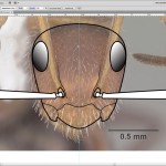
Step 1. Open the specimen photograph you plan to trace in AI. This will serve as your drawing template. Double click on the layer with the photo in the Layer Panel, and name the layer something like ‘Photo’ or ‘Specimen image’. Before closing the dialog box, also click the ‘Dim Images to’ box and put a number in between 80%-70%. Also, make sure you click the ‘Lock’ layer box. CS5 also has an option for selecting ‘Template’, which is a good idea, but not essential. When selecting your template image, look for ones with all the parts you plan to illustrate clearly showing (at least on one side of the face). For example, choose one with the full antennae showing (or at least all of one scape). Also, try for images that are positioned correctly. For example, notice on the Camponotus planatus specimen image I’m using, the right eye breaks the head outline while the left eye does not. Ideally, that discrepancy wouldn’t exist. Also, notice that the scapes block both the eyes. That’s one reason I like moving the antennal scapes down when I image my own specimens.

Specimen image of Camponotus planatus imported as a template layer into Adobe Illustrator


Step 2. Make a vertical guideline running down the middle of the face. To do this make sure the rulers are showing, then click and drag on the y-axis ruler to bring a guide out to where you need it. You can unlock the guide if you need to move it. If your specimen image is not perfectly level, unlock the photo template and rotate (r) the image until it is level, then lock it again.

Guideline running down the middle of the head.

Step 3. Create a new layer and call it something like ‘Face’.

Step 4. Draw the outline of one half of the face. For some reason, I always do the right side, perhaps because it is not obscured by the paper point. The drawing is all done using the pen tool (p). I like to draw with a 1 point stroke with rounded ends (both of which options are available in the Stroke Panel).

Start at the mid-point top at the top of the head. Drop an anchor point while holding Shift to keep the handles perpendicular to the guide, and drag the anchors out a bit towards the sides of the head. This technique keeps a nice natural curve across the head when the two halves are joined later.

Now drop your anchor point, remembering to draw out the anchor handles each time.  Drop as few anchor points as possible to make the most natural and smooth lines. You can adjust the curves as you go by using the direct select tool (a) and the convert anchor points tool (Shift+c). To continue your line, hover over the anchor point with your pen tool until you see the ‘/’ symbol, then click on it (or click and hold to draw out anchor handles).


Drawing the first curve.


Continue tracing along the outside of the face. If the eyes break the outline of the head, I just ignore them. I don’t include the mandibles until later in the process, preferring instead to follow the anterior margin of the clypeus until I hit the vertical guideline.


Step 5. Next I like to do the eyes. I use the Ellipse tool (L) while holding the Control button (to expand the ellipse from the midpoint) for the first rough approximation. Then I select the four anchor points with the direct select tool (A) and move them into place and make whatever other minor adjustments with anchor handles as necessary. Once I’m satisfied with the shape, I fill it with a gradient, then use the Gradient tool to approximate a 45 degree angle.


Drawing the eye using the Ellipse tool and Gradient tools.


Step 6. Next I draw whatever interior characters seem appropriate. In this case I do the median and lateral potions of the clypeus and the frontal carinae. For the frontal carinae, I’ve started experimenting with different width profiles available in the Stroke panel, and with the Width tool (Shift+W) to make my own custom profiles. This allows the line to taper quite elegantly.

Drawing interior characters such as the frontal carinae and the clypeus. Notice the fine tapering of the frontal carinae achieved by a custom width profile available in CS5.


Step 7. The antennae are next. In general, it is best practice in AI to draw complete closed shapes when possible. That’s what I do with the antennal condyle and torulus and whatever that part is that is basal to the condyle. Sometimes I’ll do all the antennal segments, but more often I’ll just do the scape and leave it at that.

Drawing the antennal scape.


Once I’ve outlined and closed all the shapes of the antennae, I fill them with white and arrange them forwards (Control+]) and backwards (Control+[) to get them in the right order.

Step 8. Rotate (R) the antennal scape to horizontal position. I usually group the parts that I want to rotate together. This is my personal preference, but many other illustrators seem to prefer the scape aimed towards the posterolateral corner of the head. Up to you!

Scape rotated to horizontal position. This keeps it from obstructing the face, but doesn't allow you to see how much it exceeds (if at all) the posterior margin of the head.


Step 9. Copy and flip your artwork. Select all your artwork, copy it, paste it to back (Control+B), and flip it across its vertical axis (Transform > Reflect).

Artwork is copied, pasted and flipped.


Step 10. Then, while the copy is all selected, drag it while holding down Shift (to keep it on the same axis) until the midpoints of the head line up exactly. Select pairing points where they meet at the midline with the direct select tool (A) and join them, each in turn. This is essential for when the shapes are filled with color.

Sometimes the outline will be narrower than the actual specimen image. When this happens, I select everything with the regular selection tool (V) then drag one of the sides out. This makes all the shapes wider proportionally, so it introduces a little discrepancy (of the eyes for example) in return for a more accurate head width.

Two symmetric sides of head are moved and joined to become one full head.


Step 11. Now I like to do the mandibles. I’ll do whichever is in front, then copy, paste and reflect it for the back one. Again, make sure to close the shape. Don’t worry about the inner margin overlapping the clypeus — that will get sorted out later.

Mandibles drawn as closed shapes.


Step 12. Hide the photo template layer.

Photo template layer is hidden. Notice the I also made a new layer for the scale bar.


Step 13. Fill in the head and mandibles with white (or a different color if you prefer). Then arrange different elements backwards and forwards within the layer to achieve the proper order.

Now you’re done! At this point you can adjust the artboard (CS5 only), add text, etc. If you want to add hairs, follow the directions of my illustrating ant hairs post.

All done!

Illustrating ant hairs


One of the most satisfying things to do when illustrating ants with Adobe Illustrator (AI) is to turn rather dull hairs into elegant tapered masterpieces. Hairs, or ‘setae’ as the traditionalists prefer, can be excellent characters for identification. For my introduced ant key, I need to come up with characters for distinguishing Camponotus planatus from Camponotus atriceps. I’ve coded both as having abundant long erect hairs on the head, mesosoma and gaster. But the quality of the hairs is different between these two. Those of C. planatus are stiff and thick, while those of C. atriceps are slender and flexuous. Here’s a quick post on how I drew the hairs for C. atriceps.


First thing was to import a photograph of C. atriceps from Antweb. I had to rotate it to the standard position where the back two coxae are level with each other.

Screenshot of Adobe Illustrator with specimen photo of C. atricpes placed as the first layer.


Next I created new layers for the head, mesosoma, waist and gaster, and drew the outlines using the Pen tool. I hope to post more on these basic steps of tracing specimen images in the near future.

The outlines of the specimen have been traced with the pen tool, and filled in with white.


Now I create a new layer for the hairs, and lock all of the other layers.

New 'hairs' layer is created and I zoom in a bit.


The next step is to trace the hairs. There are a few ways to do this, but the trick is to achieve a nice smooth curve. With hairs, I like to use the Pencil tool and trace on my x200 Thinkpad tablet. Before I had my tablet, though, I would probably stick with the Pen tool for these type of long flexuous hairs. If you do opt for the Pencil tool, make sure to double click on it and select a nice smoothness (I used 75%) and get rid of the ‘edit paths’ option for sure.


Hairs are traced using the Pencil tool with a tablet, but the Pen tool works well for these as well.

Once I’ve traced all the hairs on the profile outline, I hide the specimen photograph layer to see how it looks.


Here comes the cool part: making a new hair type.

  1. Use the pen tool to draw a straight line approximately as long as one of the longer hairs. Change the stroke to 0.25.
  2. Select the line and copy it (Control+C).
  3. Paste the line to the back (Control+B). This pastes the copy directly behind the original.
  4. Use the ‘Direct Select’ tool (A) and drag a selection box around the top two points (it looks like just one point because the copy is directly behind the original). Now join the two selected points. I do this by right clicking and selecting ‘Join’, but I’m sure there are other ways to get there.
  5. Again using the Direct Select tool, click on one of the bottom points. Use the arrow keys to move it a few pixels to the left. I changed the default keyboard increment (Edit > Preferences > General) to .001 in to have a bit more precision.
  6. Now select the other bottom point and move it an equal number of spaces to the right.
  7. Draw a line joining these two bottom points.
  8. Use the ‘Add anchor point’ tool (+) to drop an anchor point in the middle of this bottom line.
  9. Select the middle anchor point and move it down a few spaces. Click it and hold with the ‘Convert anchor points’ tool (Shift+C) to add a little curve to the bottom line.
  10. Fill the resulting polygon with black (or you could go for a gray if they are very light hairs if you want).
  11. Use the regular Selection tool (V) to select the whole object.
  12. Open the ‘Brushes’ window and create a new brush (lower right page icon in the window). Make it an Art Brush.
  13. Name the brush, and make sure the arrow is pointing upwards towards the pointy end (so long as you drew the hairs from the base to the tip). Save the brush library as ‘Ant Hairs’ or something like that. Sometimes if the following steps don’t work, I copy my hair to a new AI window and make a new brush. Some odd glitch or something, but sometimes it doesn’t save the brush correctly.
  14. Now select all your hairs. Easy way to do this is to make sure all the other layers are locked except for the hair layer, then do a ‘Select All’ command (Control+A). Click the new hair brush on the brush panel window, and voila. If the hairs are backwards, you may need to switch the way the arrow points in the brush options.

Lines rendered as hairs using my new C. atriceps hairs brush. Notice the fine tapering!


Now that you have the hair brush, you can paint hairs directly using the paintbrush tool. I find the paintbrush tool takes a lot longer, though, so I personally prefer using the pen or pencil tool, and then selecting all the strokes and converting them to brushstrokes with whichever ant hairs brush best suites the job.

How to improve Lucid3 thumbnails

One of the greatest assets of the Lucid3 software is its capacity to integrate thumbnails of images inserted for character states, features and taxa. Once you insert a full-size image as media, Lucid3 automatically generates a thumbnail. The default thumbnail size is 125×125 pixels, but the user can customize it in Lucid Builder. The resulting thumbnails, however, are rather low quality, and can be significantly improved by using a third party application. I use Picasa to generate my thumbnails, but I am sure there are many other programs that will do just as fine a job. So, here’s how I do it.

1. Locate your thumbnail folder in Key folder > Media > Thumbs. Remember not to change the names or structure of the files within the key folder, because this will have nasty consequences. Notice how all of the thumbnails have the “_TN.jpg” suffix appended to the filename.

2. Copy the ‘Thumbs’ folder to some safe holding space like the desktop to serve as a backup in case things go wrong.

3. Delete all of the images within the ‘Thumbs’ folder.

4. Open the application you plan to use for generating the new and improved thumbnails. In my case, I use Picasa.

5. Open the ‘Images’ folder (Key folder > Media > Images), select all the files, then export them to a new folder (e.g. ‘New Thumbnails’) as 125×125 pixel jpeg’s (or whatever size you’ve customized your key to use).

6.  Now we need to append the ‘_TN’ suffix to the new thumbnails. I use a program called ‘Bulk Rename Utility‘. Open the ‘New Thumbnails’ folder in Bulk Rename Utility. Select all the files. Type ‘_TN’ into the Suffix form of the Add box. Make sure all the files have “_TN.jpg” at the end of them in the ‘New Name’ column. Press ‘Rename’.

Bulk Rename Utility is used to append the '_TN' suffix to the new thumbnails.


7. Copy all the updated thumbnail files from the ‘New Thumbnails’ folder into the ‘Thumbs’ folder (Key folder > Media > Thumbs).


Original thumbnails generated by Lucid3

New thumbnails generated by Picasa

8. Reload your key in Builder and check for any missing thumbnails. If you find a missing thumbnail, check the file path in the media tab, and then search your ‘Thumbs’ folder for the same filename. Often I find that I need to insert a ‘_1’ before the ‘_TN’ because I’ve accidentally imported multiple copies of the same full size image into Builder, which then automatically appends the ‘_1’ to full size image in the ‘Images’ folder.

Well, the jpeg’s published here do not quite do justice to the difference in quality, but rest assured that replacing the original thumbnails with your own will dramatically improve the aesthetic and quality of your key’s media.